Create your badge
Sunday, September 27, 2009
Thursday, September 10, 2009
Sunday, May 17, 2009
Friday, May 15, 2009

Sunday, September 2, 2007
Hydrostatic testing

A hydrostatic test is the normal way in which a gas pressure vessel such as a gas cylinder or a boiler is checked for leaks or flaws. Testing is very important because such containers can explode if they fail when containing compressed gas. Hydrostatic testing is also a way in which leaks can be found in lower pressure vessels such as pipelines and plumbing.
The vessel is filled with a nearly incompressible liquid - usually water or oil - and examined for leaks or permanent changes in shape. The test pressure is always considerably more than the operating pressure to give a margin for safety, typically 150% of the operating pressure. Water is commonly used because it is almost incompressible, so will only expand by a very small amount should the vessel split.
If high pressure gas were used, then the gas would expand to perhaps several hundred times its compressed volume in an explosion, with the attendant risk of damage or injury. This is the risk which the testing is intended to mitigate.
Small pressure vessels are normally tested using a water jacket test. The vessel is visually examined for defects and then placed in a container filled with water, and in which the change in volume of the vessel can be measured by monitoring the water level. The vessel is then pressurised for a specified period and depressurised again. The water level in the jacket is then examined. The level will be greater if the vessel being tested has been distorted by the pressure change and did not return to its original volume or some of the pressurised water inside has leaked out. In both cases, this will normally signify that the vessel has failed the test.
A simpler test is to pressurise the vessel with water and physically examine the outside for leaks. Red or fluorescent dyes are usually added to the water to make leaks easier to see.
Hydrostatic testing on pipe spools is done in such a way that the Isometric drawing is divided into spools , depending on their working pressure , and then after that giving them a certain code for Identifying each Spool and the start and end of each spool to apply the adequate type of Blind flange and bolts at the required torque
Wednesday, July 18, 2007
Base Riser Installation at Berth No.1 in Ras laffan
Base Riser Installation
HFO BUNKERING FACILITY PROJECT
RAS LAFFAN
18/07/2007 , Wed.
RAS LAFFAN
18/07/2007 , Wed.
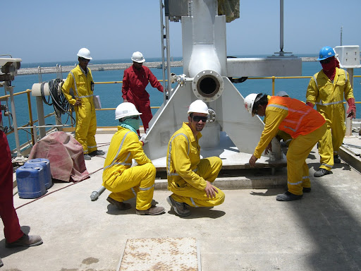
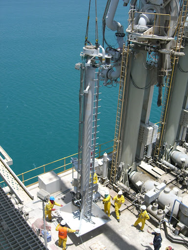
First of all , this is a historical day for MIS , Cause they have done this part of the Job , in a professional way , Error-free , Base riser the lower part of a loading arm that connects the upper
part and that connects to the main pipe that will let the fuel intended to come through it's pipe
The weight of this FMC base riser was 14.4 Tons and the crane used to lift was destined to rise
this weight at minimum distance of 26 meters from the center of the plinth that the riser will rest on, Knowing that the crane is a telescopic with a capacity of 220 tons and boom length of 68 meters
The lifting plan included another small crane to help flipping the weight to make it in the upright
Position after that scackles was tightly connected to the top of the weight , Extra cable was tightened in case of Failure , the Lifting started gradually the base riser was rising into the air
over heads till it reached the destined place over the plinth , there the metal slots and the big screws with torque wrench was waiting once laid in place the bolts were tightened from both sides and there it took it's final place waiting for the next step , the Loading arm itself.
Wednesday, July 11, 2007
SWL or WWL (Rigging Terminology)

Working load limit (WLL), safe working load (SWL) and minimum and
maximum rated loads explained
The term safe working load, (SWL) was the cornerstone of engineering, particularly with regard
to load carrying equipment, for many years.
It was generally considered to be the breaking load of a component divided by an appropriate
factor of safety giving a ‘safe’ load that could be lifted or be carried1.
About 20 years ago, however, the USA ceased using this term, because of legal implications.
The European and ISO Standards followed suit a few years later. However, while this was a
clean-cut move, for some time there has been indecision as to exactly what replacement terms
could be used.
Over the past two or three years, both the Americans and Europeans have agreed that working
load limit (WLL) should replace safe working load (SWL) in describing the capacity of items
such as hooks, slings and shackles etc.
A general definition of WLL was:
the maximum mass or force which a product is authorized to support in general service when the
pull is applied in-line, unless noted otherwise, with respect to the centreline of the product
i.e. the WLL of a component is specified by the manufacturer.
However, while the definition for working load limit was originally confined exclusively to the
manufacturer’s specified maximum load that the item could lift, it is now generally extended to
include both of the following:
· the maximum load that an item can lift;
· the maximum load that an item can lift in a particular configuration or application.
If the WLL is thought of as an assessment of the maximum load an item could lift under ideal
conditions, the SWL (if the term is going to be used) can now best be thought of as being a
derating of WLL, following an assessment by a competent person of the maximum load the item
can sustain under the conditions in which the item is being used.
Example:
If a 3 tonne (t) sling hook is attached to the bottom end of a 3 t single-leg wire rope or chain sling
in a general use application, it retains its inherent WLL of 3 t. This is its maximum load.
However, if a two-leg sling consists of two such legs, the WLL for the sling hook in such a
configuration is (1.73 x 3 t) / 2 = 2.6 t.
If the hook is to be used in a non-general application (e.g. in a mine shaft or in a hazardous
situation such as a hot environment), it may be derated further. Its SWL (as determined by the
competent person) in this particular application will be less than the original WLL of 3 t.
Some British (BS), European (EN) and International Standards (ISO) for personal protection
against falls from a height have introduced the terms maximum rated load and minimum rated
load into revisions of standards and into new standards. The maximum rated load equates to the
WLL. Some components require both the minimum and maximum rated load to be marked on
1 In the UK the Construction Lifting Operations Regulations 1961 defined it such that it actually became the load
which could legally be lifted.
the product. The minimum rated load is required where the performance of a component is
affected by a low mass. An example of a product where both a high mass and a low mass can
affect performance is a descending device.
The definitions of minimum and maximum rated load used in current drafts of European and ISO
Standards are as follows:
minimum rated load
minimum mass in kilograms of personnel, including tools and equipment, to be used with the
(insert product type), as specified by the manufacturer;
maximum rated load
maximum mass in kilograms of personnel, including tools and equipment, to be used with the
(insert product type), as specified by the manufacturer.
Subscribe to:
Posts (Atom)